Computer temperature measurement of mass concrete(First line communication)System manual
(Date of last amendment:2005.2.25)
System hardware connection
Computer temperature measurement of mass concrete(First line communication)The system is one of the most sold products,The main reason is the low price、Good real-time performance、Small operation workload、Easy installation、Product maturity,So special recommendation。
According to the actual situation of all users,Not a single project,All equipment investment can be recovered.。Because in addition to sensors,The rest is reusable,In the future, there is no need to invest in these hardware devices.。
One、Computer temperature measurement of mass concrete(Wired)Composition of the system:
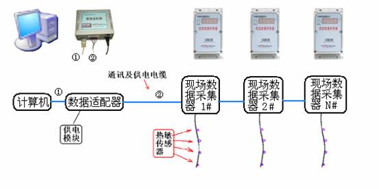
The system consists of:User computer、Computer monitoring software、Data adapter(Power supply system、Data transceiver)And power transmission line、Field data collector、Sensor composition;Optional devices are:USBturn232Modular。
Two、Brief introduction of each part:
【Power supply module】Responsible for【Data adapter】And each【Field data collector】power supply,【Power supply module】Already installed to【Data adapter】in。【Data adapter】Be responsible for【Computer】And each【Field data collector】Data communication between,【Data and power transmission line】Will each【Field data collector】and【Data adapter】Tandem up,Function of data transmission and power supply,The line should use4Core cable,The cross-sectional area of each core wire shall not be less than1Square millimetre。【Computer】Software passing【Data adapter】Control and data transmission of,Can control each【Field data collector】Operation,And collect each【Field data collector】Measurement data of,Then summarize、Handle,Save to database,And it can be dynamically displayed in real-time on the screen graph curve.,The software can print out graphs, reports, etc.。
【Field data collector】At the same time, it provides the function of displaying temperature data on the spot.。It provides convenience for construction personnel。If you want to display temperature measurement data on site,Just press【Field data collector】Upper〖display〗Button。
One【Field data collector】Can be connected at the same time1~8individual【Thermal sensor】。
Three、install:
According to the construction plane,What a site needs【Field data collector】Different quantity,Most of the time6~24only。
Field installation can be carried out before or at the same time as concrete pouring,Installation difficulty and workload are not large。
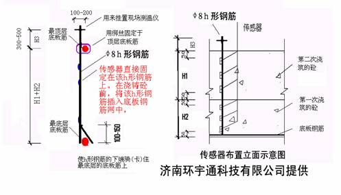
1.【Thermal sensor】According to《Temperature measurement plan》Design height of,Binding to field madehOn the steel bar for fixing,Insert vertically to the position to be tested before pouring concrete,After pouring concrete3―5hour,Can be placed【Field data collector】And will【Thermal sensor】The outgoing end of the,link up【Data and power transmission line】Can work。
2.【Field data collector】reach【Data adapter】Between【Data and power transmission line】Necessary protection is needed,Prevent rolling off during construction。【Data adapter】Between【Data and power transmission line】Placed in the concrete without setting,Generally, no special treatment is required.。(notes:【Data and power transmission line】also known as【data bus】。)
User computer is provided by user,Recommended configuration as long as it workswin98sethat will do,In addition, there must be at least one serial port(or(and)Oneusbmouth)。
【Data and power transmission line】(Also known as data bus):Self matching according to actual length,yes4Core cable,The cross-sectional area of each core shall not be less than1Square millimetre。
The following is the connection diagram of the whole system:
Of【Field data collector】
![]()
nField data collector:
The【Field data collector】The number and location of each sensor terminal block are indicated on the(The front row is from left to right:1-1,3-3,5-5,7-7,The back row is from left to right:2-2,4-4,6-6,8-8),Be careful,Sensors do not distinguish between positive and negative polarity。The unused sensor terminals are empty。
The【Field data collector】It also indicates the wire sequence number of the terminal to be connected to the data bus.(A、B、C、D),Be-all【Field data collector】Data bus terminal block of,Must be connected to the system【data bus】,And it needs to be differentiated(A、B、C、D)Line order。
Systematic【data bus】yes4Core cable,Each core section of the cable shall begreater than1Square millimetre,If the core section is too small,It will cause the increase of measurement error and the failure of data transmission.。General4The core cable has different colors,Good for differentiation(A、B、C、D)Line order。Please note that:To avoid short circuit,When wiring, the computer terminal【Data adapter】Upper“Power switch”Put“Close”state。
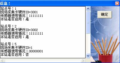
When each【Field data collector】Connected to the system bus,And it's already connected with the computer【Data adapter】After the bus terminal is connected,If the【Data adapter】Upper“Power switch”open,each【Field data collector】There should have been a power supply.,Then,Just press each【Field data collector】On the panel“Display button”,That is to say【Field data collector】HardwareID,And the measured temperature of each sensor,The display contents are as follows:
for example:Press each【Field data collector】On the panel“Display button”,Similar content will be displayed in sequence as follows:
display:3001 ßShow that【Field data collector】HardwareID;
display:---- ßdisplay4individual“-”Number;
display:1=24 ßShow measured1#The temperature value of the sensor is24℃;
display:2=25 ßShow measured2#The temperature value of the sensor is25℃;
display:3=26 ßShow measured3#The temperature value of the sensor is26℃;
display:4=27 ßShow measured4#The temperature value of the sensor is27℃;
display:5=28 ßShow measured5#The temperature value of the sensor is28℃;
display:6=29 ßShow measured6#The temperature value of the sensor is29℃;
display:7=30 ßShow measured7#The temperature value of the sensor is30℃;
display:8=E1 ßShow measured8#Sensor open or short or not in use;
in addition,Will be displayed when communicating with the computer4Equal sign:==== 。
According to the requirements of some users,The measurement range of this system has been extended to-19℃reach129℃,An example of showing a negative temperature is as follows:
display:3-16 ßShow measured3#The temperature value of the sensor is-16℃;
display100℃Examples of the above temperatures are as follows(Equal sign and hundred digit number1Share one digital tube=|):
display:3=|24 ßShow measured3#The temperature value of the sensor is124℃;
|
|
|
(Data cable connection between data adapter and computer) |
|
|
|
(Data adapter) |
|
|
|
(Wiring in field collectors,On the left is the sensor.,The connection on the right is the data bus; Please note that:The data bus is sequential,useABCDExpress) |
|
|
|
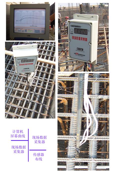
(Local pictures and connection drawings) In this picture:①Represents the data line between the computer and the data adapter; ②and㈡All represent the data bus of four core cable; ③Indicates the location of the sensor. |


(Be careful:Due to device upgrade,The device in the picture may be different from the actual device)
【Field data collector】When used on site,Can be placed in a wooden protective box,The sensor wire and data bus are threaded through the reserved holes of the wooden box.,And insert it to【Field data collector】On the corresponding terminal socket。Again【Field data collector】Fixed in wooden box with screws。Wooden box fixed onhTop of T-bar。Wooden boxes can be made on site,The structure can be made with reference to the figure below:

(chart:Wooden protection box)
About the computer side【Data adapter】
nComputer side【Data adapter】:
【Data adapter】Next to the computer,【Data adapter】The bus terminal of is connected with the data bus,DistinguishA、B、C、Dorder。
【Data adapter】There is one.9Empty serial terminal。Please use the supplied〖Special serial port connection〗,Connect it to the9Pin to serial connection。Please note that,There are usually1reach2Serial port,In use〖Special serial port connection〗You must turn off the computer's power and【Data adapter】Power supply。

(chart:Special serial port connection)
You can also use the〖Special serial port connection〗connection to【Data adapter】Upper9Empty serial port terminal,〖Special serial port connection〗The other end of the is connected to the〖USBInterface line〗Of9Pin port,Reuse〖USBInterface line〗OfUSBPort to connect to the computerUSBport。
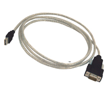
(chart:USBSerial port line)
However,Use〖USBInterface line〗Must“installUSBInterface line driver”,As shown in the figure:

in addition,If there is no serial port on the computer,Can only be usedUSBMouth and special“USBInterface line”To solve。
【Data adapter】There is also a mains connection on the,Please use the supplied〖Power supply connection〗,connection to220Volt on the mains。Please note that,In use〖Power supply connection〗take【Data adapter】Before connecting to the mains,【Data adapter】Upper〖Power switch〗Already in“Close”Location。
【Data adapter】There is also a power indicator on the,Used to indicate the switch status of the power supply。
【Serial port on computer】:
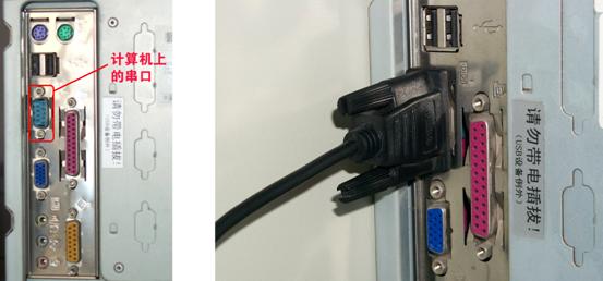
(chart:Serial port on computer,And serial port connection)
On the back of the computer,With keyboard socket、Printer jack(Parallel port)、Display data socket, etc.,One of them(Or two.)Nine pin socket,It's computer.9Pin serial port,
If【Data adapter】And computer use9For serial connection,that9One end of the pin serial port line is connected to it。Please note that,Plugged9Before the pin serial port line,Be sure to turn off the computer,Failure to do so may cause damage to your computer!
UseUSBInterface line time,No longer using computers.9Pin serial port。
Computer software
nRunning environment of software:
This software can be installed and run on the computer with the following software platform installed:
Windows98Se/WindowsMe/Windows2000/WindowsXP/Vista
At least one serial communication port is required on the computer running this software,If you don't have a serial port on your computer,have access toUSBmouth,Please consult our technical department for details。
nSoftware installation and uninstallation
nSoftware installation:
In the software installation CD,find“Mass concrete temperature monitoring system” (Pictured):

Click to install,Enter the installation interface:
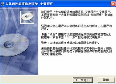
Single click【cancel】Button,Then exit this setup program。Single click【Next step】Button to go to the next step of setup。The picture is as shown in the figure:
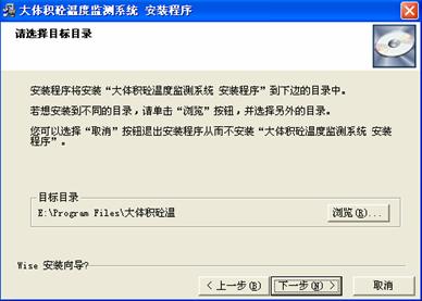
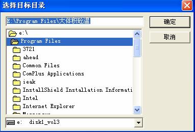
Click【cancel】Button,Then exit this setup program。Click“Previous step”Button to return to the previous installation interface。If you need to change the installation directory,Please click first."browse"Button,Can be displayedWindowsStandard dialog,To choose the installation path you want,And press“Determine”Button。Pictured:
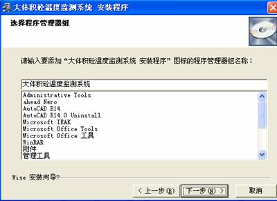
Single click"Next step"Button,Get into“Select program manager group”Interface:
click“Next step”Button,Until the installation progress bar appears:
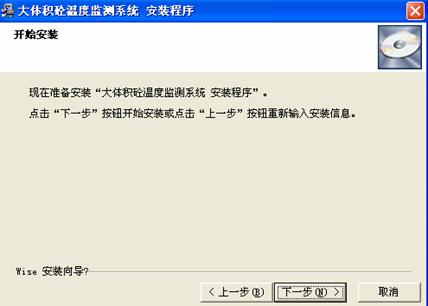
The installation progress bar behaves at different speeds in different systems:stayWindows98Se/MeFast installation in the system。stayWindows2000andWindowsXpSystem,Installation progress bar to100%In the future,Long time for software setting and adjustment,It's normal,Please wait patiently。

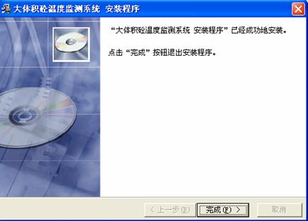
After successful software installation,The following prompt window will appear,Please click【complete】Button。
nSoftware uninstallation:
If you want to uninstall the software,Please use“Control panel”Upper“Add to/Delete program”Of“install/uninstall”attribute,Find the application name of the software in the list box,click“Add to/delete”Button,To uninstall the software。
You can also use the methods described below(Or steps)Uninstall the software:
1. Single clickwindowsDesktop【start】Button,Appear【start】menu;
2. Single click【start】Menu【program】,Appear"program"cascading menu;
3. from"program"Cascade menu click to include application【Mass concrete temperature monitoring system】Folder;
4. Click the program you want to uninstall【Temperature monitoring system for unloading mass concrete】。

Select from the interface“automatic”option,click“Next step”Button,Follow the prompts。
nUse of software
nstart-up
You can use the methods described below(Or steps)Start the software
AUse menu:
1. Single clickwindowsDesktop【start】Button,Appear【start】menu;
2. Single click【start】Menu【program】,Appear"program"cascading menu;
3. from"program"Cascade menu click to include application【Mass concrete temperature monitoring system】Folder;
4. Click the program you want to launch【Mass concrete temperature monitoring system】。
BUsing shortcuts:
You can click directly on the desktop“Mass concrete temperature monitoring system”Shortcut
nBoot interface

(Boot interface)
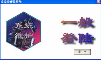 Enter in password:yanwei,click“Determine”,Enter the following login interface。Ad locum,Choice“conventional landing”,Enter the main operation interface directly,If choose“system maintenance”,Enter system maintenance“Specify background picture”Interface。
You can specify a background image here,Act as“Main interface”Base map,The background picture is preferably the plan of the bottom plate to be tested,Picture pixel size should be greater than600X800Pixels are good.,The picture format can bebmp、jpgEtc.。Set picture in“Picture preview”Box to preview。
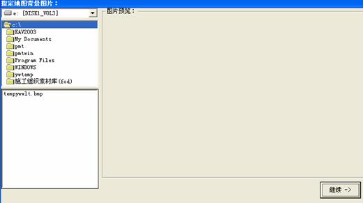
click“Continue”Get into“Set up”window。
nSetup window

In the settings window,Provides the location of the set test point、Parameters and other functions。

among:
nAdd monitoring points After pressing this button,Move the mouse in the settings screen on the left,

And shock the mouse in a proper place.,A new site will appear,And the parameter configuration screen of the site will pop up.:
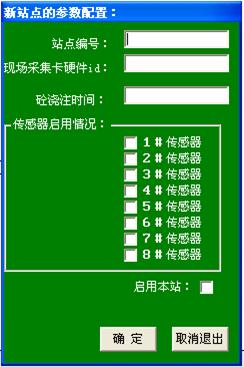 Set the following data here according to the actual situation:
Site number:Add a new site number
Hardware of field acquisition cardid:According to the actual hardware of the field acquisition cardidNo. to fill in,4Digit number,Be true and correct,otherwise,The system will not communicate properly。
Concrete pouring time:Can fill in、Or not.,As a note only。
Sensor enable:According to the“Field data collector”Actual sensor configuration on,Select the sensor bit to use。
Please note that:“Field data collector”The sensor numbers on are sequential(Or not in order)。
nEnable this station:Determine if the station is enabled。
nAdjust the position of each station:After pressing this button,Drag the site to be adjusted with the mouse,To change its position in the drawing。
nSet parameters of each station:After pressing this button,Click the site to be adjusted with the mouse,You can reset the parameters of this site。
nDelete a station:Press this button,Click todeleteSite,Pop up the delete site dialog box:
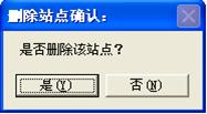
click“Determine”,Delete it。
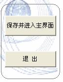
nSave and enter the main interface:Save the settings just made and enter the main interface of the software。
nSign out:Exit the software。
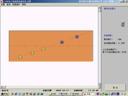
nMain operation interface:
nUse of menus
nSetup menu
click“Set up”Under the menu“system parameter”
nAdjust date time :This function provides“Counter table”function:The system time can be adjusted manually.,To make the date and time of the computer match the actual date and time at that time。
nCommunication parameter setting
“Communication port”It can be set according to the actual situation.,Select port。Recommended here“Automatic acquisition”Button,After pressing the button,The system displays the following prompt:
Follow the prompts,The configuration of communication port can be completed automatically.。
“push parameter”:Please use the default value。
“Acceptance parameter”:Please use the default value。
nSet the automatic inspection interval You can set the automatic inspection interval according to your own needs。(Default is recommended:30Minute)
nSign out You can quit.“system parameter”Set up
nstart-upwindowsRun the software automatically when
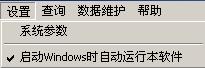
It's a switch menu.,You can set whether to startwindowsRun the software automatically when。If set to“yes”(Check mark),You can run the software automatically the next time the computer starts,And enter the main interface。
nParameters of each monitoring point
Set the position of each monitoring point、number、HardwareID、Sensor configuration、Site enabling status, etc.,Please see“system maintenance”。
nAlarm temperature difference setting
The temperature difference alarm threshold between adjacent sensors connected to the same data collector can be set。The scope is0reach99,The default value is25degree。The alarm prompt is as shown in the figure.:
nEnable automatic data backup
The checkmark in front of the menu always works,Every day11:59and23:59Around the clock,Automatic backup of measurement data。This is specially set for data security。
click“Set up”Under the menu“system parameter”
nQuery menu

Click on the site in the drawing,The same menu will appear。
nParameter setting of the station:After selecting a station,Click this button,Parameters of the station can be set.。
nImmediate inquiry:After selecting a station,Click this button,The temperature of the station can be queried immediately。
nQuery all sites now:Click this button,The temperature of each enabled site can be queried immediately。
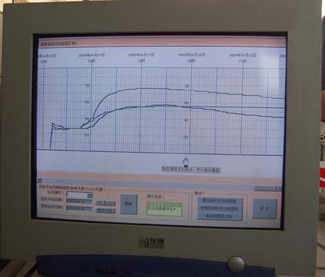
nMeasured temperature curve:Click this button,It can display the,Plot of the actual measured temperature at the site:
 Print pattern(Reduction)
In the figure above, you can“Setting of drawing start date and drawing duration days”;You can choose how to output(Original scale prints the current drawing;Half width scale prints the current drawing、Output to picture file, etc.)。
In the above picture,You can drag left and right with the mouse,To change the position of the current view,You can also use the scroll bar below the graphic,To change the position of the current view。
nReport form:click“Report form”Button,The following screen appears(Resolution up to0.1):
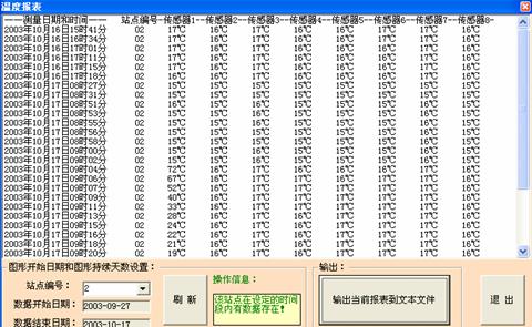
In the figure above, you can“Graph start date and graph duration days”Set up”;Sure“Output current report to text file”,Then print out。
nView the main configuration of each site:Here you can see the detailed configuration of each site。
nBe careful:Click on each site of the main operation interface,Can be set or queried,As shown in the figure:(The specific operation is the same as above)

nData maintenance menu
click“Data maintenance”Lower“Data maintenance”
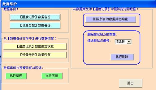
nData backup
【Temperature recording】Data backup:Yes, yes.“Temperature recording”Data for backup。The specific operation is as follows:
Click this button,Eject“Specify data backup file name”Dialog box:
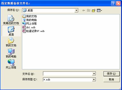
In the figure above, you can name and save the file to be backed up.;click“Preservation”Button to save。
n【Setting parameters】Data backup:Yes, yes.“Setting parameters”Data for backup。
The specific operation is the same as above。
nfrom【In the data backup file】Data recovery
n【Temperature recording】Data append recovery:You can append previously saved data to“Temperature recording”Database
Click this button,Eject“Backup filename”Dialog box:
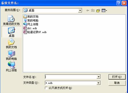
Find previously saved data files,click“open”Button,Then you can append the data to the current“Temperature recording”Database。
【Setting parameters】data recovery:Can be restored to previously saved“Parameter setting”state。
The specific operation is the same as above。
nDatabase defragmentation repair and compression
nExecution and arrangement:Defragment database files。
nExecution compression:Compress database files。
nFrom database file【Temperature recording】Delete the specified data in:
nDelete all data and initialize:Delete existing“Temperature recording”All data in the database,And initial database to empty state。
nDelete data for the specified site:stay“Please select a site number”Select the number of the site to delete from the drop-down list,click“Execution deletion”You can“Temperature recording”Delete all data from the specified site in the database。
nSign out:Sign out“Data maintenance”window
nHelp menu(slightly)
nOther instructions:
nAfter the software enters the main interface,That is to say, it can automatically and regularly check,It can be changed by setting the periodic inspection interval.“Timing interval”。Default is recommended(30Minute)。
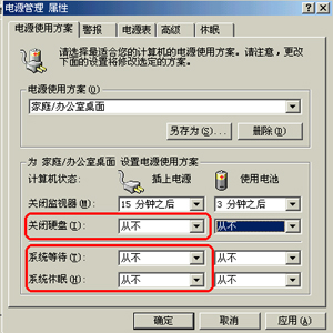
Please pay special attention:On the computer“Power management”Attribute,take【System sleep attribute】and【Close hard disk】attribute、【System standby properties】All set as“never”。otherwise,It is possible that your computer will automatically go to sleep or the hard disk will not work,The software can not be automatically checked。To do this, right-click the blank space on the desktop of the system.,Appear“Display attribute”:
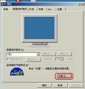
Click on“Screen saver”option,Then click【Set up】,Appear“Power management”attribute,Pictured:
Please send“Close hard disk”、“System dormancy”Property set to“never”,System standby is not allowed、dormancy。
nDuring the measurement period,〖Computer software〗and〖Field data collector〗、〖Data adapter〗All in working condition。
nAfter each query,If there is communication failure,Fault information will be displayed automatically,You should find out the cause of the faulty site,Generally, the following items need to be checked:1、Corresponding to this site〖Field data collector〗HardwareIDIs the number correct,2、Is it broken?,3、Short circuit,4、〖Field data collector〗Damaged or not。
Emphasize:Because the equipment is used on the construction site,Poor working environment,To prevent equipment and cables from being damaged、Squash。In case of communication failure,Be sure to find out why,Timely repair。When arranging communication cables,Place it in the wet concrete surface,It's a particularly effective way.(If it goes along the steel bar,Will be better)。Another way is to thread the wire into the plastic pipe。
No joint is allowed in the middle of the cable,If it can't be avoided,Ensure reliable connection at the joint,All joints must be waterproof、Anti short circuit。
n〖Field data collector〗Wooden case should be added outside for protection,Prevent the ambient temperature from overheating,To prevent〖Field data collector〗Be rolled。Outside the wooden box,Put on a plastic bag,It can effectively avoid rain and splashing、Dew。Always avoid flooding。
nThe〖Field data collector〗Cascade function,Theoretically, it can be cascaded at most255individual。The most practical cascading instances that have been applied in the construction site are44individual。
nThe〖Field data collector〗and〖Data adapter〗The distance between them should not be greater than1km(Related to the section and quality of data lines), 〖Data adapter〗and〖Computer〗The distance between them is not greater than5m。
The following features need to be customized to provide:
nThe customization function of the software can be provided throughInternetFunction of remote viewing curve and data report(To use this feature,Need1、The computer running the temperature measurement system should be connected to theInternet,2、Need internetIPAddress support/Or rent our server/Or useEmail),if necessary,Please contact our technical department。
nThe customization function of the software can be provided throughInternetFunction of sending data to designated mobile phone via SMS(To use this feature,The computer that needs to run the temperature measurement system should be connected to theInternet),if necessary,Please contact our technical department。
nThe customization function of the software can be provided throughGSMFunction of module card to send data to designated mobile phone via SMS(To use this feature,Additional purchase requiredGSMModule card、Mobile user card),if necessary,Please contact our technical department。
nThe software has been added with any custom logic function.,Used to control the heat source, such as:Electric blanket、Steam valve、Automatic opening and closing of hot air blower, etc.。Need to cooperate with our company's remote control relay control。
Edition(Software and hardware upgrade at the same time)History:1994,1995,1997,2001,2003,2005,2007.
technical parameter:
data collector:(Industrial standard)
1、Working environment temperature of equipment:-20℃~80℃;
2、measuring range:-15℃~125℃(2005year2month1Daily adjustment),At the measured temperature<-19℃Time,displayLL,At the measured temperature>129℃Time,displayHH;
3、Distance from data adapter:Cross section of data line>1mm2Time,The measured distance value is1000mRange;If the distance is too long,The data bus between the data adapter and the first field data collector can be appropriately bold.CLine andDLine,Some of our customers are connected in parallel.CLine andDLine,The effect is very good.。
4、Maximum number of sets:Data collectors connected to the same data adapter are best controlled in32Only within;
5、Number of sensors that can be connected per data collector:1~8individual;
6、Data collector to sensor length:0~10m;11~30m(Customized);
7、Power supply mode:Data adapter bus parasitic;
8、Measurement method:Automatic inspection/Trigger inspection;
9、Eight wayADTotal time of measurement conversion<1s,Data resolution accuracy0.01,Effective1.00,error<=±1℃±1word;
Data adapter:
1、Working environment temperature of equipment:-20℃~80℃,Place next to computer;
2、Interface with computer:Support at the same timeCOMMouth andUSBmouth,Automatic adaptation;
3、Distance from computer<=8m,Distance from field data collector<=1200m
(Related to data line);
4、supply voltage:AC170V~240V,50~60HZ,Market electricity;
5、Data receiving and sending instructions;
6、What is provided to each data collector through the data bus is14.8VSafety voltage of;
7、Data adapter has short circuit automatic protection function;
Jinan huanyutong Technology Co., Ltd.
Email: ywjn@0531hyt.com
website1:http://www.0531hyt.com
Linear telephone:(0531)8715-6618
Automatic fax server:(0531)8716-2717
To work in an office:Jinan Jiwei Road90Number1#Commercial building